
[AWS][EKS] Best practice for load balancing - 1. Let’s start with an example from Kubernetes document
This article is sharing the best practice for doing load balancing on Amazon EKS, learn what is advantage and disadvantage of using different controller. We will discuss more detail about what is the problem of using default Kubernetes service deployment as mentioned on official document.
Understand the default Kubernetes load balancing
An overview of externalTrafficPolicy
I have many occurrences to see Kubernetes administrators are not very familiar with the Kubernetes network flow, and feel struggling about that when they need to diagnose networking issue, especially for users using managed Kubernetes cluster service. But I think that’s normal to see this gap because it reflects Kubernetes is doing encapsulation perfectly, causes you are unable to easily troubleshoot any real-world failures unless you had deeply understand its design.
Before walking through the detail about the load balancing, it is required to understand the fundamental knowledge of Kubernetes load balancing and its effect when defining your YAML files.
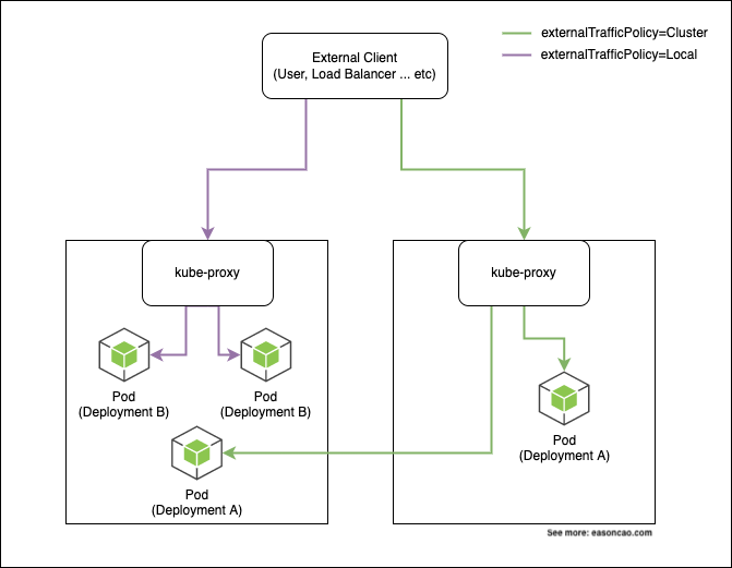
In the Kubernetes, it provides External traffic policy, so you can set this field (spec.externalTrafficPolicy) in your Kubernetes service deployment to control the flow, and decide how to route the traffic from external. Kubernetes offers two options for this policy: Cluster and Local, let’s have a deep overview to see how it works:
By default, the kube-proxy is performing this layer of load balancing by using iptables. Based on the Pods you are running, it will create rules in your iptables and uses random mode (--mode random) to perform the load balancing based on the probability. For example, if you have 3 Pods need to be distributed, kube-proxy will take the responsibility to add required iptables rules with defined probability, and try to balance the load:

I am not going to drill down into too much detail as it can increase the complexity of this article, however, if you are interested to learn how this translation happens, you can review the iptables rules on your host to see what’s going on.
# An example of iptables rules
-A KUBE-SVC-XXXXX -m comment --comment "default/app" -m statistic --mode random --probability 0.20000000019 -j KUBE-SEP-AAAAAA
-A KUBE-SVC-XXXXX -m comment --comment "default/app" -m statistic --mode random --probability 0.25000000000 -j KUBE-SEP-BBBBBB
-A KUBE-SVC-XXXXX -m comment --comment "default/app" -m statistic --mode random --probability 0.33332999982 -j KUBE-SEP-CCCCCC
-A KUBE-SVC-XXXXX -m comment --comment "default/app" -m statistic --mode random --probability 0.50000000000 -j KUBE-SEP-DDDDDD
-A KUBE-SVC-XXXXX -m comment --comment "default/app" -j KUBE-SEP-EEEEEE
As mentioned in Figure 1, when externalTrafficPolicy=Cluster, it can have a scenario will route the traffic to other Nodes if you deploy Pod(s) on them. By relying on the iptables rules, this policy can accomplish the load balancing by redirecting them to other Nodes. In theory, this can bring the traffic jump out of the original Node.
When externalTrafficPolicy=Local, it limits the traffic only can be redirected on the same Node; however, the behavior of doing load balancing through the iptables still happens. If you have multiple Pods running on the single Node, the traffic can be routed to one of them.
Deep dive into the load balancing behavior - An example from K8s document
Let’s see an example mentioned at official Kubernetes document1:
apiVersion: v1
kind: Service
metadata:
  name: nginx-svc
  labels:
    app: nginx
spec:
  type: LoadBalancer
  ports:
  - port: 80
    protocol: TCP
  selector:
    app: nginx
If you use AWS as cloud provider and deploy the service, it generally will create an Elastic Load Balancer (Classic Load Balancer) and provide the traffic load balancing. The Elastic Load Balancer will be managed by the in-tree load balancer controller2, which is implemented in Kubernetes source code; hence, you can simply provision the Elastic Load Balancer on AWS seamlessly.
Looks familiar, right? The example above is quite common if you find tutorial on somewhere. Maybe that is exactly same configuration running in your production environment.
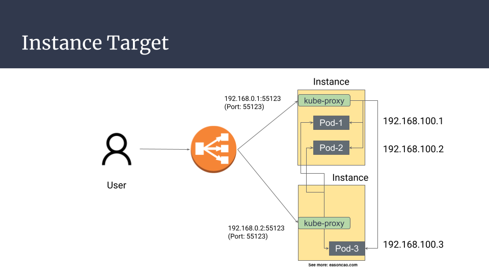
But here is the problem: by default, Kubernetes implements another layer of load balancing, which is backed with kube-proxy. Let’s say if you have two worker nodes (Node-1 and Node-2), and each node have Pods running on it (Pod-1, Pod-2 on Node-1; Pod-3 on Node-2), using default option (externalTrafficPolicy=Cluster). On AWS, the traffic flow generally is representing as below:
Case 1
The default Kubernetes service will expose your application with a specific service port to provide external accessibility (NodePort), and establish relevant iptables rules to perform NAT traslation by replacing the IP address of the destination field.
With this design, this can be a happy case if kube-proxy doesn’t redirect the request to other host, which can be outlined as:
client -> Load Balancer -> Node-1 (NodePort) -> iptables rules -> Pod-1 on Node-1
Case 2
However, what if the iptables forward the traffic to other Nodes?
client -> Load Balancer -> Node-1 (NodePort) -> iptables rules -> Pod-3 on Node-2
On the other hand, if you deploy a Kubernetes service like this, the traffic flow can be routed as two particular phenomena:
As you can see, no matter what it is, the behavior seems like doesn’t provide a better route because it definitely increases the number of hops for the traffic flow.
What about externalTrafficPolicy: Local? Does it work better?
Follow the example as mentioned in the previous paragraph, let’s say if you have two Pods (Pod-1 and Pod-2) running on the same Node (Node-1). The traffic flow of this policy generally can be breaking down as below:
client -> Load Balancer -> Node-1 (NodePort) -> iptables rules -> Node-1 (Target Pod-1)
client -> Load Balancer -> Node-1 (NodePort) -> iptables rules -> Node-1 (Target Pod-2)
When load balancer move the request to the backend (Node-1), the probability to forward the request by iptables rules to the Pod-1 and Pod-2, is 50% chances.
On the other hand, the traffic firstly pass through the Elastic Load Balancer, and do the routing again in the system level (iptables), which means the architecture will perform the load balancing twice.
With no doubt, it did not offer the best path for the traffic routing.
The reason why you will see your targets are failing the health check even Pods are running
If externalTrafficPolicy=Local and you have multiple Nodes running behind your Elastic Load Balancer, you probably will see some Nodes will fail the health check, which can be expected.
That’s because if some Node doesn’t run the service’s backend Pods so it cannot pass the health check.
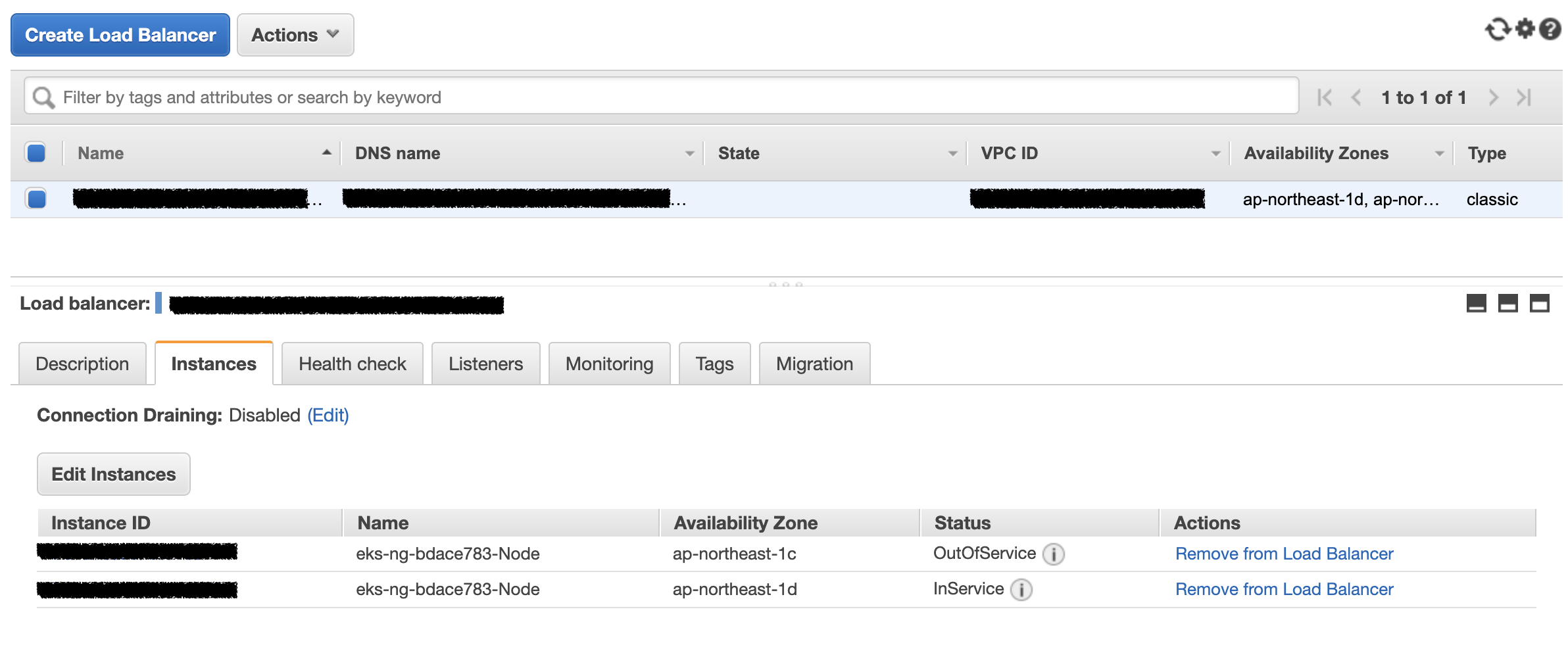
In general, it doesn’t impact anything because the ELB will ensure only healthy targets can be routed; however, in this case, it doesn’t perfectly distribute the load with Elastic Load Balancer and offer high availabilty when we have multiple Pods. If the Node down, it can impact all Pods running on it.
What’s wrong with externalTrafficPolicy?
So, looks like using
externalTrafficPolicy=Clusteris a good option?
Imagine you have a long running connection is jumping out of the first Node, unfortunately, the first Node is having issue such as hardware failure, intermittent connectivity problem … etc. In the end, it is going to be down. In this case, if any existing connections forwarded from other Nodes, the connections will be impacted and cannot response back to the origin correctly. In general, the Node down can cause the packet loss because the connection route is established in the middle:
(If you have established connection passed the Node, here is an example of the breaking route situation if the Node-1 in the middle is down.)
client -> Load Balancer ->
Node-1 (NodePort)-> iptables rules -> Target Pod-2 on Node-2
If you reviewed the flow of Figure 3, connections can be routed to different paths and it can be hard to predict once you deployed many Pods. It also increase the complexity if you would like to trace the networking flow during the problem diagnostic.
When having a large scale scenario (e.g. deploy 100, 500 even 10,000 Pods), this also can potentially bring the system level issue, or, result in the packet loss, such as network latency increased due to kernel needs to compare several iptables rules when a new connection comes in; or, reach out to the kernel limits for the networking stack, because Linux kernel needs to track of them when working with iptables, and insert the rules on the system level. One common issue is to fill out the connection tracking table (conntrack) of the Linux kernel when the scale grows.
Summary
In this article, it explains the behavior of load balancing on Kubernetes. This article also brings you an overview and learn what issue can occur if you follow the default Kubernetes example to deploy your Elastic Load Balancer.
Now we have deep-level understanding of the Kubernetes load balancing, let’s start with more discussion regarding the load imbalancing problem with the current architecture on Amazon EKS in the next article.
- Best practice for load balancing - 1. Let’s start with an example from Kubernetes document
- Best practice for load balancing - 2. imbalanced problem
- Best practice for load balancing - 3. what controller should I use
References
-
Kubernetes service - Type LoadBalancer ↩
-
Kubernetes source code - aws_loadbalancer.go ↩
Share on
Twitter Facebook LinkedInIs that useful? Let me know or buy me a coffee
 一次性支持 (ECPay)


Leave a comment